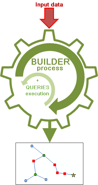
Schematic builders build the content of the schematic diagrams.
Schematic builder execution
Any schematic diagram template is based on a schematic builder. Schematic builders are used to build/update the content of diagrams implemented by a schematic diagram template. They expect specific data and a specific context from which they are able to generate/update the schematic diagrams.
The schematic builder on which a schematic diagram template is based is specified at schematic diagram template creation.
Learn about how to configure the schematic diagram template builder
Three types of builders are provided with Schematics: Standard builder, Network Dataset builder, and XML builder. Each predefined schematic builder has been developed to deal with specific input data.
Moreover, whatever the builder is, Schematics can also be configured to get diagrams which content mixes schematic features resulting from the builder process with other schematic features coming from custom queries.
Schematic builders and input data
The Standard builder
The Standard builder works from any GIS feature class/layer or object table
Working from network features
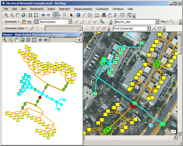
Because it is able to decode geometric network and network dataset topology, the Standard builder is especially dedicated to work with GIS feature classes organized into a geometric network or a network dataset. It allows you to quickly generate schematic diagrams in a minimum amount of time from any set of network features that are currently highlighted in an ArcMap document further to a selection or a trace operation. This is a useful builder for the typical utility-type and transportation companies that deal with geometric networks or network datasets.
Learn more about the Standard builder when working with network features
Working by querying spatial or non spatial data
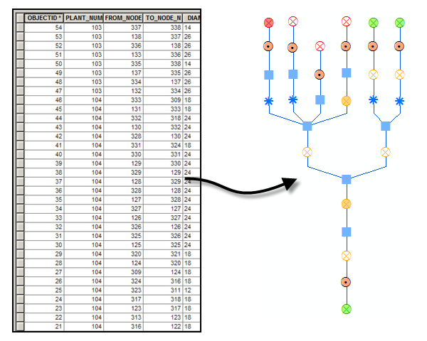
The Standard builder can also be used to generate schematic diagrams whose whole contents are built from custom queries. These custom queries can operate on any type of database. The main prerequisite for working with custom queries is that the data stored in the database must contain the information required for connectivity—that is, the information required to identify the origin (start) and extremity (end) of each link in the diagrams that will be generated. Structured Query Language (SQL) is used to write the queries needed to retrieve the desired data
The XML builder
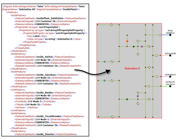
The XML builder works from XML data based on the XMLBuilderDiagram XML Schema Definition file. It is the builder to use if you work with external applications such as industry applications (for example, Network Engineer), ERPs (for example, SAP), PLMs (for example, Matrix One), or analysis packages (for example, CYME). It allows you to avoid developing specific interfaces that are costing a lot and not easy to maintain. This builder requires custom code to be written that generates the XML that is passed into the builder.
The Network Dataset builder
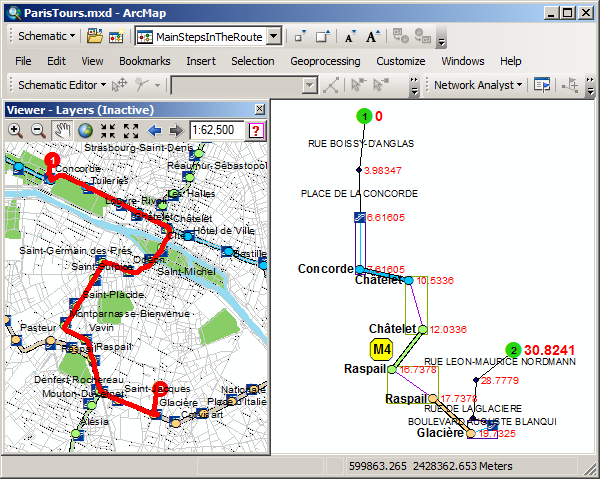
The Network Dataset builder works from solver results on network datasets. It expects solved network analysis layers as input (such as solved route, service area, closest facility, or vehicle routing network task analysis). It can be configured to merge network element junctions which appear several times in the input solved network analysis, and so get those junctions represented by single schematic nodes in the resulting schematic diagram.
Mixing any schematic builder result with custom queries result
Any schematic builder can also be used to generate mixed diagrams that contain:
- Schematic features coming from the specific input data/context with which it is supposed to deal (for example, a solved network analysis layer for the Network Dataset builder, XML data for the XML builder, or a set of GIS features highlighted in a map for the Standard builder)
- Other schematic features built from custom queries that directly operate from those newly created schematic features or on any other type of data.
For example, suppose you have a geometric network that represents the main installations and connections for an electric network. Beside this geometric network, you also have non-spatial object tables which detail security equipments for each installation—switches, short circuit detectors, security components, etc. In this case, Schematics can be configured to generate elaborate diagrams which mix schematic features coming from the geometric network and schematic features coming from queries that execute on the non spatial tables to automatically retrieve all the security equipments related to each network installation in the diagram.
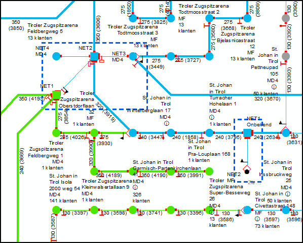
The following capture illustrates this scenario. It represents a piece of diagram among the multiple schematic diagrams that have been created using ArcGIS Schematics. The installations and connections coming from the electric geometric network are represented by green, blue and grey schematic nodes and schematic links. The queried security equipments related to each installation are represented by small red symbols and black flags that display near the associated installation nodes. Those equipments are implemented by a particular type of schematic features called node-on-link schematic features.
